I believe that my group were quite successful in getting our idea across during the presentation.
A number of points were made (good & bad) based on our animation.
The combination of audio & visuals was a ood mixture. The feedback given was that the animation had a perfect balance and did not contain any irrelevant information.
One of the bad points was that during the audio I had abreviated the word Carburetor to Carb. This was out of habbit and as nobody (including me) noticed this wasnt changed earlier.
Another idea that was given to us was at the start of the animation, the audio started quite quickly. When the audio got edited for the final time, pieces of audio were edited out. Including the opening speech. If it is decided that the museum would like to use our animation then this can easily be edited.
I am proud of what was said about the groups animation. There were no major problems, and it seemed to be a mixed reception on whether the voice over had the correct pitch and speed.
Another point made to the entire class was the fact that they had little contact with any of the groups. This is definatly a major learning curve for the future. By working alongside the museum, it would have made the creation of the animation easier where we wouldnt have had to guess what they would have preffered content wise.
But this was probably the most vital piece of feedback we were given.
Thursday, 10 December 2009
Tuesday, 8 December 2009
Evaluation
Group:
At the start of this project I will admit that I was worried with the group that I was set. This was due to no-one living local to the university so I wasn't sure how easy it would be to set group meetings.
As time went on though, I realised that I was within a highly motivated team. Everyone got stuck in, did what they were asked and showed alot of interest in the project. It helped that we all wanted the same from this project, to learn off of each other and produce the best we could.
I will admit there were arguments within the group. But we showed maturity in that it didn't effect our work. I
Shuo, Rob and Kiel all produced the best they could and I believe it shows with the work we have managed to produce.
My Work:
I was set a number of tasks that varied in what software I had to use. So this project has enabled me to learn a few new tricks.
With the modelling of the piston, the shapes looked correct. The problem came when importing them into a different version of 3DS, as you can see from the video, one of the cam shafts is very untidy, and it apparent in the video.
Due to time running out we decided to stick with what we had.
By overlooking what the others were modelling I did manage to learn more techniques. Rob showed how to position lights and setup realistic shadows; he also taught me an animation technique using wireframe and the slice modifier (shown on the sparkplug earlier in the blog)
Given more time then the only piece I would change on the animation is showing how the engine works within the lawnmower. Considering none of the group had any prior knowledge on the 2 stroke engine I am very pleased with the outcome.
Environment added

Kiels environment works really well alongside the rest of the animation. He has managed to produce a good environment which doesn't look out of place when the lawnmower was added.
There are a couple of faults with the final animation though. Due to different files being used for rendering, the cam on the piston changes colour.
Another problem is with when the lawnmower is within the environment, I was asked to stop the lawnmower, so that it allowed the viewer to take in what was being seen. I took this literally so just used a static shot. What I didn't realise was that Kiel meant stop the lawnmower but keep the camera moving. So this has to be rendered again.
The final problem is with the audio, from feedback it was said that the speech was too fast, and gave the viewer no time to take in the information.
I decided to record the audio again, but due to illness the sound quality was extremely poor.
Instead I have decided to cut the initial audio into more precise information to give a better impression to the viewer.
To get the final shot correct on the animation with the environment, i had to adjust the curve editor to stop the wheels spinning. I wasn't able to completely stop that from happening, all I could do was set a segment where they didn't move before it would loop back again.
This was due to the animation being setup by Rob, and as I was unsure of where to move pieces I had to improvise. This worked well and enabled me to complete the editing succesfully.

Thursday, 3 December 2009
Editing
Once the animations had been rendered within 3DS, it was down to me to edit the video to coincide with the audio.
The idea was to slow down the specific sections within the video editor. I don't believe this is a good idea as it will gradually reduce the quality of the videos. This is due to the frame rate that we have used (30fps). I believe that the sections of video should have been edited within 3DS before rendering. Once I have shown the group the completed video I hope to bring up the problem of video quality at the next meeting.
I decided to use Sony Vegas Studio 9.0 to edit the video as this gave me the most control over editing the footage. The main control required was the slowing down and speeding up of the video.
At present this is the video that has been produced, the only thing missing is the environment at the end which Kiel is producing (Garden including trees, shed and grass)
Tuesday, 24 November 2009
Animation
The task of animation has been left for group meetings and in class. This way each group member can express their feelings if they believe the animation does not quite work.
The video editing and rendering has been tasked to me.
Utilising Robs knowledge has been key, it was his diea to animate the engine being created through wireframe and overlapped with the model.
Once Rob had positioned the lighting and the camera he produced this opening shot.
I had previously learnt from this and replicated it when displaying the spark plug earlier in the blog. Even though I may not have the current knwoledge, I am finding it increasingly important to learn off other group members.
We found that there was a problem with the 2nd stage of the animation. The 2 shots did not line up due to the cameras being miss aligned.
For this I decided that the easiest way would be to rescale the engine to get the dimensions as close as possible to the initial render. Another problem was the shadow in the initial render had been deleted from the 2nd stage.
Before:
After:
By looking closely at the end of before video, you can see that the piston shaft doesn't match up with the Cam. It appears to be rotating on its own.
The group were stumped by this, but after going through the key frames I found that the problem was with the keyframes not aligning, so after a few rotations the shaft moved further and further out of line.
Problem solved:
The next stage was to animate the top of the Piston and to start animating the flow of liquids and gases within the engine.
We decided to use the slice modifier to animate the liquids and used.
This video gives a rough indication of how the piston will be animated. The movement still needs to be fine tuned and textures also have to be added.
The video editing and rendering has been tasked to me.
Utilising Robs knowledge has been key, it was his diea to animate the engine being created through wireframe and overlapped with the model.
Once Rob had positioned the lighting and the camera he produced this opening shot.
I had previously learnt from this and replicated it when displaying the spark plug earlier in the blog. Even though I may not have the current knwoledge, I am finding it increasingly important to learn off other group members.
We found that there was a problem with the 2nd stage of the animation. The 2 shots did not line up due to the cameras being miss aligned.
For this I decided that the easiest way would be to rescale the engine to get the dimensions as close as possible to the initial render. Another problem was the shadow in the initial render had been deleted from the 2nd stage.
Before:
After:
By looking closely at the end of before video, you can see that the piston shaft doesn't match up with the Cam. It appears to be rotating on its own.
The group were stumped by this, but after going through the key frames I found that the problem was with the keyframes not aligning, so after a few rotations the shaft moved further and further out of line.

Problem solved:
The next stage was to animate the top of the Piston and to start animating the flow of liquids and gases within the engine.
We decided to use the slice modifier to animate the liquids and used.
This video gives a rough indication of how the piston will be animated. The movement still needs to be fine tuned and textures also have to be added.
Textures
I was given the task of producing textures for the animation. Rob had already produced the gradient environment background so it was down to me to produce the lower engine casing, flywheel, upper engine as well as textures for the fluids within the engine.
It is important not to overpower the viewer with the textures, if this happens then it will take their concentration away from what the video is describing.
We could have produced a full chrome engine that was really shiny. But this could be a distraction.
We also wanted each part of the engine to be contrasting so that it was easiyl distinguishable for the viewer.
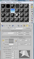
The lower engine case was to have a matte colour that did not shine.We did not want the base to be smooth either as looking at the original reference pictures show that the engine was quite bumpy.
This is the texture that I was able to produce within photoshop. A bump map was added to it within 3DS and by adjusting the settings I was able to produce a suitable texture.

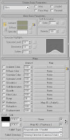
The upper engine was to have a slightly shinier surface but not so shiny that it would react like a mirror.
The group decided against producing such a reflective material due to the rendering times. So it was decided to keep this fairly basic. It was noticed that some groups were having problems rendering due to the size of the animation and the materials they were using.
The flywheel was to have a lsightly different colour to allow it to stand out. I went for a brown color that was more reflective than the engine. From the previous research gathered on engine components it showed that the flywheel had a shinier texture so we decided to follow this as a guideline.
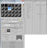
The material for the sparkplug was setup using IDs. This allowed me to save space within the materiale editor and use one slot to produce the multiple materials for one object.
A spark plug has fairly plain colours so I decided to use basic colours for the centre and the tip of the object.
I then used a lighter version of the lower engine casing material and edited it to produce a shinier effect.

Other important textures produced were for the inside of the engine. I went for an oily look for this, I decided to keep it quite dark due to the lack of the light within the inside of the engine

A the radial gradient tool was used within Photoshop to produce the texture of the combustion within the engine.

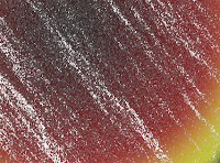
Using a variety of filter effects such as plastic wrap, noise and gaussian blur to produce the texture for the air mixture within the engine.

I have produced two copies of the combustion texture as an opacity map could be added to the white version to produce a more realistic looking animation.
The final texture produced was the smoke. This was very simple to produce, using the clouds filter and altering the hue, brightness and contrast.

It is important not to overpower the viewer with the textures, if this happens then it will take their concentration away from what the video is describing.
We could have produced a full chrome engine that was really shiny. But this could be a distraction.
We also wanted each part of the engine to be contrasting so that it was easiyl distinguishable for the viewer.
The lower engine case was to have a matte colour that did not shine.We did not want the base to be smooth either as looking at the original reference pictures show that the engine was quite bumpy.
This is the texture that I was able to produce within photoshop. A bump map was added to it within 3DS and by adjusting the settings I was able to produce a suitable texture.


The upper engine was to have a slightly shinier surface but not so shiny that it would react like a mirror.

The group decided against producing such a reflective material due to the rendering times. So it was decided to keep this fairly basic. It was noticed that some groups were having problems rendering due to the size of the animation and the materials they were using.
The flywheel was to have a lsightly different colour to allow it to stand out. I went for a brown color that was more reflective than the engine. From the previous research gathered on engine components it showed that the flywheel had a shinier texture so we decided to follow this as a guideline.


The material for the sparkplug was setup using IDs. This allowed me to save space within the materiale editor and use one slot to produce the multiple materials for one object.
A spark plug has fairly plain colours so I decided to use basic colours for the centre and the tip of the object.

I then used a lighter version of the lower engine casing material and edited it to produce a shinier effect.

Other important textures produced were for the inside of the engine. I went for an oily look for this, I decided to keep it quite dark due to the lack of the light within the inside of the engine

A the radial gradient tool was used within Photoshop to produce the texture of the combustion within the engine.


Using a variety of filter effects such as plastic wrap, noise and gaussian blur to produce the texture for the air mixture within the engine.

I have produced two copies of the combustion texture as an opacity map could be added to the white version to produce a more realistic looking animation.
The final texture produced was the smoke. This was very simple to produce, using the clouds filter and altering the hue, brightness and contrast.

Sound Clip Part 2
I have managed to finally complete quality editing of the audio for the animation.
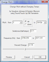
By using the software Audacity I was able to produce the sound clip so that the voice appeared slightly higher pitched, which also increased the clarity of the speech. This will benefit the viewers as it will become more understandable.
Within Audacity minimal changes were made, just adjusting the Octave of the voice from a C to an F was enough to get the result I was seeking.
Before:
After:
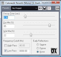
One final effect was added to the audio which would amplify the voice more. If kept as it is the audio appeared flat and quite boring. So it was decided to import the audio back in Cakewalk Sonar 6 and add a reverb effect.
Final Audio (quality editing):
Even though the quality of the audio has now been edited there is still work to do with it. Once the animation has been completed the audio will be adjusted to keep in time with the animation. At the moment some parts of the audio appear slow, and other parts too fast.
By using the software Audacity I was able to produce the sound clip so that the voice appeared slightly higher pitched, which also increased the clarity of the speech. This will benefit the viewers as it will become more understandable.
Within Audacity minimal changes were made, just adjusting the Octave of the voice from a C to an F was enough to get the result I was seeking.
Before:

After:

One final effect was added to the audio which would amplify the voice more. If kept as it is the audio appeared flat and quite boring. So it was decided to import the audio back in Cakewalk Sonar 6 and add a reverb effect.

Final Audio (quality editing):
Even though the quality of the audio has now been edited there is still work to do with it. Once the animation has been completed the audio will be adjusted to keep in time with the animation. At the moment some parts of the audio appear slow, and other parts too fast.
Monday, 23 November 2009
Sound Clip
I decided to edit together the voice recordings using the software Magix: audio cleaning lab.
I found that the original recording had background noise and editing this out did reduce the clarity of the audio.
(Original)
The initial idea was to edit the voice so that it would appear deeper. But this idea has been scrapped after it was found trying to present my voice deeper would further reduce the clarity of what information was being discussed.
A version of the audio has been edited with the pitch of the voice being made higher. This produced a better quality sound and produced clearer dialect throughout the recording.
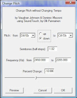
To produce the higher pitch I used Cakewalk Sonar 6. This is because I could not find a feature that would be suitable to do this within Magix.

A pitch shift editor was added to the clip which would allow me to set how high or how low the audio should be.

The next editor added was Graphic Dynamics, this would allw me to select individual parts of the track and choose whether the voice should be high or low. This didn't add much to the clip so it was decided to remove as the more editors added the bigger the file size would be.

The final editor added to the audio was the FxEq. This allowed me to set how loud specfic points of the audio should be. It worked in the same way as the Graphic Dynamics. This worked well as the start of the recording has a lower velocity than the middle and ending.

The problem here with using these effects is the fact that alot of audio disturbance has been added.
For this reason this copy cannot be used. The background noise has been added due to the quality of the initial recordings. If a sound recording device had been used then much of the initial background noise would not have been recorded and quality would not have deteriated in such a way.
At present the audio will be edited until a satisfactory result has been identified.
I found that the original recording had background noise and editing this out did reduce the clarity of the audio.
(Original)
The initial idea was to edit the voice so that it would appear deeper. But this idea has been scrapped after it was found trying to present my voice deeper would further reduce the clarity of what information was being discussed.
A version of the audio has been edited with the pitch of the voice being made higher. This produced a better quality sound and produced clearer dialect throughout the recording.
To produce the higher pitch I used Cakewalk Sonar 6. This is because I could not find a feature that would be suitable to do this within Magix.

A pitch shift editor was added to the clip which would allow me to set how high or how low the audio should be.

The next editor added was Graphic Dynamics, this would allw me to select individual parts of the track and choose whether the voice should be high or low. This didn't add much to the clip so it was decided to remove as the more editors added the bigger the file size would be.

The final editor added to the audio was the FxEq. This allowed me to set how loud specfic points of the audio should be. It worked in the same way as the Graphic Dynamics. This worked well as the start of the recording has a lower velocity than the middle and ending.

The problem here with using these effects is the fact that alot of audio disturbance has been added.
For this reason this copy cannot be used. The background noise has been added due to the quality of the initial recordings. If a sound recording device had been used then much of the initial background noise would not have been recorded and quality would not have deteriated in such a way.
At present the audio will be edited until a satisfactory result has been identified.
Group Meeting 5
At present the group is still on track at meeting deadlines so that we are able to complete an efficient animation within the time period.
Modelling for the environment will now take place after succesfully completing the modelling of the engine. This task has been delegated to Shuo as her modelling skills are of a higher standard and we can rely on her to produce what we are looking for.
The environment will consist of a lawnmower.
The other tasks to be completed by next week are the textures (which I have been set to complete). These textures will include metal textures for the engine. I have also been asked to start editing the audio for the animation.
Next week the group will focus on animating the Piston, animating the fluid movement within the engine, and if there is time then the lawnmower will be animated.

Monday, 16 November 2009
Cams & Spark plug
The shape of the cam is very basic
For this I decided to use a cylinder and cut away the unnecessary parts. The problem I found was that it left gaps between vertices.

The solution was to use poly mode and draw in polys so that the entire model was connected together.


The shape of this model is quite rough, but due to the cams not being in direct view of the camera the detail did not have to be high.
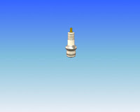
The spark plug was a much harder shape to model. I decided to use a box modelling technique to produce this.
By using information found on the internet I was able to setup a reference plane to guide for me to follow.

To start with I had a cylinder split into multiple height sections. Using both the movement tool as well as the scaling tools I was able to adjust the edges and manouvre the vertices into position. The scale tool was beneficial as it allowed me to move the outside edges and keep the rounded shape.

The group agreed that the sparkplug would be used towards the animation. Here Rob was able to teach me how to use the slice modifier, using a simple technique he taught me that it could be used to display work in an interesting way within animation.
For this I decided to use a cylinder and cut away the unnecessary parts. The problem I found was that it left gaps between vertices.

The solution was to use poly mode and draw in polys so that the entire model was connected together.


The shape of this model is quite rough, but due to the cams not being in direct view of the camera the detail did not have to be high.
The spark plug was a much harder shape to model. I decided to use a box modelling technique to produce this.
By using information found on the internet I was able to setup a reference plane to guide for me to follow.

To start with I had a cylinder split into multiple height sections. Using both the movement tool as well as the scaling tools I was able to adjust the edges and manouvre the vertices into position. The scale tool was beneficial as it allowed me to move the outside edges and keep the rounded shape.

The group agreed that the sparkplug would be used towards the animation. Here Rob was able to teach me how to use the slice modifier, using a simple technique he taught me that it could be used to display work in an interesting way within animation.
Saturday, 14 November 2009
Group Meeting 4
The first week of modelling the engine has been completed. The group have encountered a number of problems while fitting the individual models together. The scaling of the models are wrong. Even though the dimensions of each piece are correct they need to be adjusted slightly to fit each piece correctly.
This is largely down to the poor views of the reference photos, and shows how important it is to have sufficient material to work from.


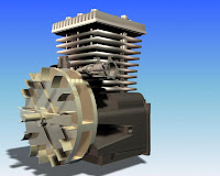
Due to the poor quality, I decided to research the styles of Pistons and find one that matched the style within our 2 stroke engine.

This picture was perfect for detailing what parts of the engine may look like. For me I had to use a similar style Piston and crank shaft. I did not go into full detail on the crank shaft purely as the base and top wouldn't be seen for detail to be noticed.
While building the engine it was noticed that we had not created all parts to the engine. This included the cams of the crank shaft
The Compression chamber for which the Piston would move within as well as a spark plug.
These would all be vital in producing a successful representation of how a 2 stroke engine works.
Kiel was delegated the modelling of the chamber while I was given the task of producing the cams. I also put myself forward for producing the sparkplug. I felt that I couldn't really show what I have learnt while using 3DS and the sparkplug would be a challenge.

This is largely down to the poor views of the reference photos, and shows how important it is to have sufficient material to work from.


Due to the poor quality, I decided to research the styles of Pistons and find one that matched the style within our 2 stroke engine.

This picture was perfect for detailing what parts of the engine may look like. For me I had to use a similar style Piston and crank shaft. I did not go into full detail on the crank shaft purely as the base and top wouldn't be seen for detail to be noticed.
While building the engine it was noticed that we had not created all parts to the engine. This included the cams of the crank shaft
The Compression chamber for which the Piston would move within as well as a spark plug.
These would all be vital in producing a successful representation of how a 2 stroke engine works.
Kiel was delegated the modelling of the chamber while I was given the task of producing the cams. I also put myself forward for producing the sparkplug. I felt that I couldn't really show what I have learnt while using 3DS and the sparkplug would be a challenge.

Thursday, 12 November 2009
Piston Part 3
The final stage of the piston was to to produce the bolts. I decided as these were not a set model for the group that I would produce a basic shape. I did want to produce a model that resembled a screw thread on it, but after alot of thinking I decided against it as I couldnt find a suitable way of producing such a model.
The main bolt was produced by extruding the centre of a cylinder twice. Even though the thread is now ridged, we can add a smoothing material at a later stage to produce a better effect.

The 2nd bolt used the same technique but instead pushed the centre of the bolt inwards.

The main bolt was produced by extruding the centre of a cylinder twice. Even though the thread is now ridged, we can add a smoothing material at a later stage to produce a better effect.

The 2nd bolt used the same technique but instead pushed the centre of the bolt inwards.

Piston Part 2
following the succesful modelling of the Piston head, it was now time to produce the crank shaft, and the connecting bolts.
The chances of seeing the bolts during the animation is slim, but by producing them it gives the group alternative directions to go with the animation.
The crank shaft uses a simple shape. For this I decided to produce the outline of the shaft using the line tool.

Then use the Extrude modifier to produce the 3 dimensional shape.

The problem with the extrude tool (as stated earlier) is that the object will be ridged. As I need a smooth object for the crank shaft I decided to use the cut tool (Poly) within editable poly to produce more edges to allow me to easily manipulate the edges into a smooth shape.

I added detail by extruding a section of the shaft (centre). Using a cylinder I was then able to use the boolean to bore the mounts for the bolts to fit.

Piston
When the work was delegated it was agreed that any modelling should use minimal polygons. Rob had made us aware that once animation was added as well as textures to any models, the render times would increase substantially.
My task was to create the Piston. I started with a cylinder and set the dimensions based upon the scale agreed during the groups previous meeting.
I then split the cylinder into multiple sections, this was to enable me to match up all indentations from the head of the piston.
By setting the cylinder to an editable poly it allowed me to manipluate specfic points of the model.
My first thought was to extrude the indentations on the piston. The problem with this is the surface becomes ridged and would mean I would lose the initial smooth texture.

My next idea was to move the points manually, this would allow for detail to be kept but the problem would be the time taken to keep the symmetry all the way round the piston.
The third option was to select an edge and use the Loop function to make sure the same set of edges round the cylinder were selected and use the scale tool to draw areas in and keep the smoothness of the object.

To keep the squareness of the indentations of the piston head I used the movement tool on the selected edges to model them into place.

The next stage was to bore the centre of the piston head. My initial idea was to delete the vertices individually. A problem I found with doing this was it offered no depth within the piston.

I realised that the best way to produce the depth within the base of the Piston as well as save time was to use the boolean modifier which allows a model to be subtracted from another.
This technique was also used on the face of the piston where the bolts mount to.

Tuesday, 3 November 2009
Work Delegation
The group have decided to split up each task into smaller chunks where possible. The advantage of managing the work like this is that it allows each member to prove the quality of the modelling standards and animation standards which will could be a good way for each of us to learn new techniques through feedback off group members.
A rough storyboard has been created (see Group Meeting 3) but at a later stage a higher standard copy will be produced.
After group meeting 3 I was given the task of producing a voice over to give the group an outline of what should be done with the models during animation.
The modelling tasks have also been delegated.
Elaine - Carburetor
Kiel - Master cylinder
Robert - Magnetic flywheel & bottom end of cylinder
I have been given the task of producing the Piston and Crank Shaft.
Group Meeting 3
Following on from previous group discussions, we decided to concentrate on producing ideas on what we believe is most important to create for this video.
We decided that the video should be short, this is because we do not want the viewers becoming bored of what they are watching. For this reason, we have decided that the video should be to the point and run for no longer than 2 minutes.
From research that we have gathered, many videos based on the 2 stroke engine are covered within a similar time scale.
Within this time, it will also enable the group to explain and get the knowledge across to the viewer in reasonable depth.
The group have also discussed how to enhance the viewers experience. This included:
Use of visual effects - to produce a more appealing element to the video, if the video is dull then this will come across in the viewers attitude towards the video.
Use of speech - Having a video with sound effects would be simple, but then the viewer would find it very hard to follow what is taking place and going away feeling they have gained information. For this the group believe it is important to use audio commentary as well as visual elements to make the experience as understandable as possible.
The group have decided to concentrate on the side of the engine, this is because it will represent in greater detail the information being explained within the audio. It will also limit the chances of mistakes being made with the visual elements of the video.
Another visual element discussed by the group was the use of tags and arrows so that the viewer knows what area of the engine to concentrate on as the audio goes through its cycle.

Thursday, 22 October 2009
Group Meeting 1 & 2
The first 2 meetings didn't go particularly well. We didn't manage to get the entire group in one place. This was due to travel problems for a couple of the group members.

In the first meeting me and Kiel decided to take initiative and decide that the group should work on recreating a 2 stroke engine.
We have discussed what styles of shots could be used and what kind of information could be displayed.
In the 2nd meeting we got to know Shuo and discuss the previous weeks ideas with her.

Evaluation
Even though this is my first time at creating a human head. I am slightly disapointed with what I have created. There are a number of errors in the modelling as well as the texturing.
I struggled at understanding how the nose should be created and in the end it was a mess, it was far too angular and was too big in scale compared to the reference plates.

From this picture it is also possible to see that the head isn't completely in line with the reference plates either.
I believe that given more time I could produce a more satisfying piece of work. But as time was always going to be a factor with this project it makes me think that in the future I should possibly use my time more wisely to allow for more alterations on each stage.
Another problem is how I connected the ears, I stated earlier in my blog that I had problems with the welding tool and only certain vertices would attach. In the future I will try to keep such a difficult object simple. Even though I managed to get the initial detail of the ear quite high, it lead to problems. Due to these problems it lead to lost time and an end product that was of poor quality. The back of the ear is overly stretched and lets down the final piece.

In the future I will also look into becoming more familiar with the UVW mapping. With a mixture of the poor unwrapping as well as poor formations for the quads this lead to textures being stretched.

This made me realise jsut how important each stage is, and the initial "simple" stage of the topology is probably the most important if you want an incident free and easy route to completing such a piece of work.
Subscribe to:
Comments (Atom)